

Vedi le specifiche per i dettagli del prodotto.
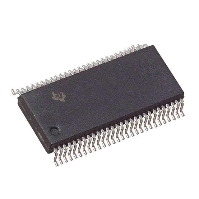
SN74ALVTH16827DLR
Product Overview
- Category: Integrated Circuit (IC)
- Use: Logic Level Translator
- Characteristics: High-speed, low-voltage, 20-bit bus transceiver with 3-state outputs
- Package: 56-pin TSSOP (Thin Shrink Small Outline Package)
- Essence: Translates signals between different voltage levels in digital systems
- Packaging/Quantity: Tape and Reel, 2500 units per reel
Specifications
- Supply Voltage Range: 1.2V to 3.6V
- Input Voltage Range: 0V to VCC
- Output Voltage Range: 0V to VCC
- Maximum Operating Frequency: 400MHz
- Propagation Delay: 2.5ns (max) from A to B, 2.9ns (max) from B to A
- Output Drive Strength: ±12mA
- ESD Protection: Human Body Model > 2000V, Machine Model > 200V
Detailed Pin Configuration
The SN74ALVTH16827DLR has a total of 56 pins. The pin configuration is as follows:
- OEAB
- A1
- A2
- A3
- A4
- A5
- A6
- A7
- A8
- A9
- A10
- GND
- B1
- B2
- B3
- B4
- B5
- B6
- B7
- B8
- B9
- B10
- VCCB
- DIR
- GND
- Y1
- Y2
- Y3
- Y4
- Y5
- Y6
- Y7
- Y8
- Y9
- Y10
- VCCA
- GND
- A11
- A12
- A13
- A14
- A15
- A16
- A17
- A18
- A19
- A20
- VCCB
- B11
- B12
- B13
- B14
- B15
- B16
- B17
- B18
Functional Features
- Bidirectional voltage translation between 1.2V and 3.6V systems
- Supports both push-pull and open-drain outputs
- 3-state outputs allow multiple devices to share a common bus
- Low power consumption with Ioff feature for power saving in idle mode
- Schmitt-trigger inputs for noise immunity
- ESD protection for robustness against electrostatic discharge
Advantages and Disadvantages
Advantages: - High-speed operation allows for efficient data transfer - Wide supply voltage range enables compatibility with various systems - 3-state outputs facilitate bus sharing among multiple devices - Low power consumption helps conserve energy - Robust ESD protection ensures reliability in harsh environments
Disadvantages: - Limited to 20-bit bus width, may not be suitable for larger systems - Requires careful consideration of voltage levels to prevent signal distortion - Relatively large package size may limit use in space-constrained applications
Working Principles
The SN74ALVTH16827DLR is a logic level translator designed to enable communication between digital systems operating at different voltage levels. It utilizes a combination of MOSFETs and control circuitry to achieve bidirectional voltage translation.
The device has two supply voltage pins, VCCA and VCCB, which are connected to the respective systems operating at different voltage levels. The DIR pin controls the direction of data flow, allowing signals to be translated from system A to system B or vice versa.
When the DIR pin is set to logic high, the A-side inputs (A1-A20) are connected to the B-side outputs (Y1-Y10), enabling translation from system A to system B. Conversely, when the DIR pin is set to logic low, the B-side inputs (B1-B18) are connected to the A-side outputs, facilitating translation from system B to system A.
The SN74ALVTH16827DLR also features 3-state outputs, which can be disabled by asserting the OEAB pin. This allows multiple devices to share a common bus without interfering with each other's signals.
Detailed Application Field Plans
The SN74ALVTH16827DLR is commonly used in various digital systems where voltage level translation is required. Some specific application fields include:
- Microcontrollers: Facilitating communication between microcontrollers
10 domande e risposte comuni relative all'applicazione di SN74ALVTH16827DLR nelle soluzioni tecniche
Sure! Here are 10 common questions and answers related to the application of SN74ALVTH16827DLR:
Q: What is SN74ALVTH16827DLR? A: SN74ALVTH16827DLR is a 20-bit buffer/driver with 3-state outputs, designed for low-voltage (1.65V to 3.6V) applications.
Q: What is the maximum operating frequency of SN74ALVTH16827DLR? A: The maximum operating frequency of SN74ALVTH16827DLR is typically around 400 MHz.
Q: Can I use SN74ALVTH16827DLR in both input and output applications? A: Yes, SN74ALVTH16827DLR can be used as both an input buffer and an output driver.
Q: What is the purpose of the 3-state outputs in SN74ALVTH16827DLR? A: The 3-state outputs allow multiple devices to share a common bus without interfering with each other.
Q: What is the power supply voltage range for SN74ALVTH16827DLR? A: SN74ALVTH16827DLR operates within a power supply voltage range of 1.65V to 3.6V.
Q: Can SN74ALVTH16827DLR tolerate overvoltage on its inputs? A: No, SN74ALVTH16827DLR is not designed to tolerate overvoltage on its inputs. It is recommended to stay within the specified voltage range.
Q: Is SN74ALVTH16827DLR compatible with both TTL and CMOS logic levels? A: Yes, SN74ALVTH16827DLR is compatible with both TTL and CMOS logic levels, making it versatile for various applications.
Q: What is the output drive strength of SN74ALVTH16827DLR? A: SN74ALVTH16827DLR has a typical output drive strength of ±12mA.
Q: Can I use SN74ALVTH16827DLR in high-speed data transmission applications? A: Yes, SN74ALVTH16827DLR is suitable for high-speed data transmission due to its low propagation delay and fast switching characteristics.
Q: Are there any specific layout considerations for using SN74ALVTH16827DLR? A: It is recommended to follow the layout guidelines provided in the datasheet to ensure proper signal integrity and minimize noise coupling.
Please note that these answers are general and may vary depending on the specific application and requirements. Always refer to the datasheet and consult with an expert for accurate information.