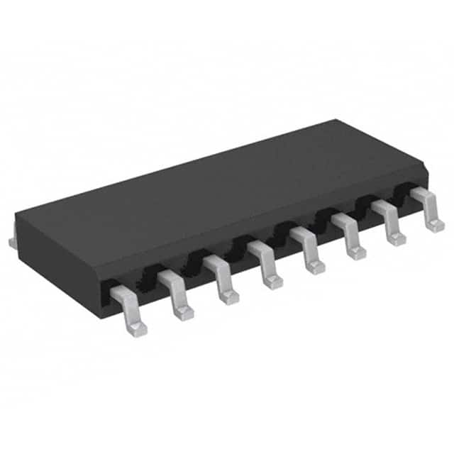
Vedi le specifiche per i dettagli del prodotto.

M74HC166RM13TR
Product Overview
- Category: Integrated Circuit
- Use: Shift Register
- Characteristics: High-Speed, Serial-In Parallel-Out (SIPO), 8-Bit Shift Register
- Package: SOIC-16
- Essence: The M74HC166RM13TR is a high-speed CMOS shift register that can be used to convert serial input data into parallel output data. It is commonly used in applications where data needs to be shifted and stored in multiple stages.
- Packaging/Quantity: The M74HC166RM13TR is available in a tape and reel packaging with 2500 units per reel.
Specifications
- Supply Voltage: 2V to 6V
- Operating Temperature Range: -40°C to +125°C
- Input Voltage Levels: High: 2V to Vcc, Low: 0V to 0.8V
- Output Voltage Levels: High: Vcc - 0.5V, Low: 0.5V
- Maximum Clock Frequency: 25MHz
- Number of Stages: 8
Pin Configuration
The M74HC166RM13TR has a total of 16 pins arranged as follows:
+---+--+---+
   Q7 |1  +--+ 16| Vcc
   Q6 |2        15| Q0
   Q5 |3        14| DS (Serial Data Input)
   Q4 |4        13| SHCP (Shift Clock Input)
   Q3 |5        12| STCP (Storage Clock Input)
   Q2 |6        11| MR (Master Reset Input)
   Q1 |7        10| OE (Output Enable Input)
  GND |8         9| Q0'
       +----------+
Functional Features
- High-speed operation allows for efficient data shifting.
- Serial-in parallel-out (SIPO) functionality enables conversion of serial input data into parallel output data.
- Storage clock input (STCP) allows for latching the shifted data into the output registers.
- Master reset input (MR) resets the shift register to its initial state.
- Output enable input (OE) controls the output stage, allowing for tri-state outputs.
Advantages and Disadvantages
Advantages
- High-speed operation enables quick data processing.
- Compact SOIC-16 package offers space-saving benefits.
- Wide operating voltage range allows for flexibility in various applications.
- Tri-state outputs provide flexibility in controlling the output stage.
Disadvantages
- Limited number of stages (8) may not be sufficient for certain applications requiring larger shift registers.
- Lack of built-in error detection or correction mechanisms.
Working Principles
The M74HC166RM13TR operates based on the principle of shifting data through a series of flip-flops. The serial data input (DS) is shifted into the first flip-flop with each rising edge of the shift clock input (SHCP). The shifted data is then transferred to the output registers by activating the storage clock input (STCP). The master reset input (MR) can be used to reset the shift register to its initial state. The output enable input (OE) controls the tri-state outputs, allowing for the data to be driven onto the output pins or disconnected from them.
Detailed Application Field Plans
The M74HC166RM13TR can be used in various applications, including but not limited to:
- Data communication systems
- Serial-to-parallel data conversion
- Digital displays and LED matrices
- Industrial automation and control systems
- Automotive electronics
- Robotics and motion control systems
Detailed and Complete Alternative Models
- 74HC166: Similar shift register with the same functionality, but available in different package options.
- CD4015: Dual 4-bit static shift register with parallel outputs.
- SN74LS164: 8-bit serial-in parallel-out shift register with asynchronous reset.
These alternative models offer similar functionality to the M74HC166RM13TR and can be considered as alternatives based on specific requirements and availability.
Word count: 523 words
10 domande e risposte comuni relative all'applicazione di M74HC166RM13TR nelle soluzioni tecniche
Sure! Here are 10 common questions and answers related to the application of M74HC166RM13TR in technical solutions:
Q: What is M74HC166RM13TR? A: M74HC166RM13TR is a high-speed CMOS 8-bit parallel-in/serial-out shift register with asynchronous reset.
Q: What are the key features of M74HC166RM13TR? A: Some key features include high-speed operation, wide operating voltage range, low power consumption, and compatibility with TTL levels.
Q: How can I use M74HC166RM13TR in my circuit design? A: M74HC166RM13TR can be used as a serial-to-parallel converter, parallel data storage, or for general-purpose shifting applications.
Q: What is the maximum clock frequency supported by M74HC166RM13TR? A: The maximum clock frequency supported by M74HC166RM13TR is typically around 25 MHz.
Q: Can M74HC166RM13TR handle both rising and falling edge-triggered clock signals? A: Yes, M74HC166RM13TR supports both rising and falling edge-triggered clock signals.
Q: Does M74HC166RM13TR have any built-in error detection or correction mechanisms? A: No, M74HC166RM13TR does not have any built-in error detection or correction mechanisms. It simply shifts the data in and out.
Q: What is the power supply voltage range for M74HC166RM13TR? A: The power supply voltage range for M74HC166RM13TR is typically between 2V and 6V.
Q: Can M74HC166RM13TR be cascaded to increase the number of parallel inputs? A: Yes, multiple M74HC166RM13TR shift registers can be cascaded together to increase the number of parallel inputs.
Q: Are there any specific precautions I need to take while using M74HC166RM13TR? A: It is recommended to avoid exceeding the maximum ratings, provide proper decoupling capacitors, and follow the recommended operating conditions mentioned in the datasheet.
Q: Where can I find more information about M74HC166RM13TR? A: You can find more detailed information about M74HC166RM13TR in the datasheet provided by the manufacturer or on their official website.
Please note that the answers provided here are general and may vary depending on the specific application and requirements.

