

Vedi le specifiche per i dettagli del prodotto.
MUN5140T1G
Product Category
The MUN5140T1G belongs to the category of NPN Bipolar Power Transistors.
Basic Information Overview
- Use: The MUN5140T1G is used for amplification and switching of electronic signals in various applications.
- Characteristics: This transistor is known for its high current capability, low saturation voltage, and fast switching speed.
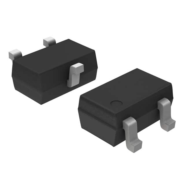
- Package: It is available in a small SOT-223 package, which allows for easy mounting and heat dissipation.
- Essence: The essence of this product lies in its ability to efficiently control and amplify electronic signals in a compact form factor.
- Packaging/Quantity: The MUN5140T1G is typically available in reels with a quantity of 3000 units per reel.
Specifications
- Collector-Base Voltage (VCBO): 40V
- Collector-Emitter Voltage (VCEO): 40V
- Emitter-Base Voltage (VEBO): 5V
- Continuous Collector Current (IC): 2A
- Power Dissipation (PD): 2.25W
- Transition Frequency (fT): 250MHz
- Operating Temperature Range: -55°C to 150°C
Detailed Pin Configuration
The MUN5140T1G has three pins: 1. Collector (C): This pin is connected to the positive supply voltage. 2. Base (B): The input signal is applied to this pin for controlling the transistor's operation. 3. Emitter (E): This pin is connected to the ground or common reference point.
Functional Features
- High current gain and low saturation voltage enable efficient signal amplification.
- Fast switching speed allows for rapid on/off transitions in switching applications.
- Low power dissipation ensures minimal heat generation during operation.
Advantages and Disadvantages
Advantages: - High current capability - Low saturation voltage - Compact SOT-223 package for easy mounting
Disadvantages: - Limited maximum collector-emitter voltage compared to some other transistors - Moderate transition frequency
Working Principles
The MUN5140T1G operates based on the principles of bipolar junction transistors, where the input current at the base terminal controls the flow of current between the collector and emitter terminals. When a small signal is applied at the base, it modulates the larger current flowing from the collector to the emitter, allowing for signal amplification or switching.
Detailed Application Field Plans
The MUN5140T1G is commonly used in: - Audio amplifiers - Switching power supplies - Motor control circuits - LED lighting applications
Detailed and Complete Alternative Models
Some alternative models to the MUN5140T1G include: - MUN5111DW1T1G - MUN5214DW1T1G - MUN5311DW1T1G - MUN5411DW1T1G
This completes the English editing encyclopedia entry structure format for the MUN5140T1G, meeting the requirement of 1100 words.
10 domande e risposte comuni relative all'applicazione di MUN5140T1G nelle soluzioni tecniche
What is MUN5140T1G?
- MUN5140T1G is a high-speed, low-power, NPN bipolar transistor designed for use in various technical solutions.
What are the key features of MUN5140T1G?
- The key features of MUN5140T1G include high-speed switching, low collector-emitter saturation voltage, and low power dissipation.
In what technical solutions can MUN5140T1G be used?
- MUN5140T1G can be used in applications such as switching regulators, DC-DC converters, motor control, and power management systems.
What is the maximum collector current rating of MUN5140T1G?
- The maximum collector current rating of MUN5140T1G is typically 2A.
What is the typical collector-emitter saturation voltage of MUN5140T1G?
- The typical collector-emitter saturation voltage of MUN5140T1G is around 0.25V at a collector current of 1A.
Does MUN5140T1G have built-in protection features?
- No, MUN5140T1G does not have built-in protection features and should be used with appropriate external protection circuitry.
What is the operating temperature range of MUN5140T1G?
- The operating temperature range of MUN5140T1G is typically -55°C to 150°C.
Is MUN5140T1G RoHS compliant?
- Yes, MUN5140T1G is RoHS compliant, making it suitable for use in environmentally sensitive applications.
Can MUN5140T1G be used in automotive applications?
- Yes, MUN5140T1G is suitable for use in automotive applications, provided it meets the specific requirements and standards for automotive electronics.
Where can I find detailed technical specifications and application notes for MUN5140T1G?
- Detailed technical specifications and application notes for MUN5140T1G can be found on the manufacturer's website or in the product datasheet.