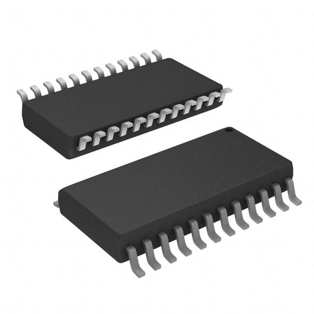
Vedi le specifiche per i dettagli del prodotto.

Encyclopedia Entry: 74F675ASC
Product Information Overview
- Category: Integrated Circuit (IC)
- Use: Digital Logic Comparator
- Characteristics: High-speed, low-power consumption
- Package: Small Outline Integrated Circuit (SOIC)
- Essence: Performs binary comparison of two 4-bit numbers
- Packaging/Quantity: Available in reels of 250 units
Specifications
- Supply Voltage: 4.5V to 5.5V
- Operating Temperature: -40°C to +85°C
- Input Voltage Range: 0V to Vcc
- Output Voltage Range: 0V to Vcc
- Propagation Delay: 6ns (typical)
- Power Dissipation: 50mW (typical)
Detailed Pin Configuration
The 74F675ASC has a total of 16 pins arranged as follows:
__    __
   A1 | 1  16 | Vcc
   A2 | 2  15 | B1
   A3 | 3  14 | B2
   A4 | 4  13 | B3
  GND | 5  12 | B4
   LT | 6  11 | GT
   EQ | 7  10 | LTG
  CLK | 8   9 | EQG
       --------
Functional Features
- Performs binary comparison of two 4-bit numbers (A and B)
- Outputs three signals: LT (Less Than), GT (Greater Than), and EQ (Equal)
- LT is active LOW when A < B
- GT is active LOW when A > B
- EQ is active LOW when A = B
- Supports cascading for larger bit-width comparisons
Advantages and Disadvantages
Advantages: - High-speed operation allows for quick comparison of binary numbers - Low-power consumption makes it suitable for battery-powered devices - Small package size saves board space in compact designs
Disadvantages: - Limited to 4-bit comparisons, not suitable for larger bit-widths - Requires external clock signal for synchronous operation
Working Principles
The 74F675ASC is a digital logic comparator that compares two 4-bit binary numbers (A and B). It utilizes internal circuitry to perform the comparison and generates three output signals: LT, GT, and EQ. These signals indicate whether A is less than, greater than, or equal to B, respectively.
The comparator operates synchronously with an external clock signal (CLK) and produces the output signals based on the input values at each clock cycle. The LT, GT, and EQ outputs are active LOW, meaning they are driven to a logic low state when the corresponding condition is met.
Detailed Application Field Plans
The 74F675ASC is commonly used in various applications that require binary number comparison, such as:
- Digital signal processing systems
- Microcontrollers and microprocessors
- Arithmetic and logic units (ALUs)
- Data sorting and searching algorithms
- Error detection and correction circuits
Its high-speed operation and low-power consumption make it suitable for applications where quick and efficient binary comparisons are required.
Detailed and Complete Alternative Models
Some alternative models that offer similar functionality to the 74F675ASC include:
- 74LS85: 4-bit Magnitude Comparator
- 74HC688: 8-bit Identity Comparator
- 74ACT297: 8-bit Magnitude Comparator
- CD4073B: Triple 3-input AND Gate
These alternatives can be considered based on specific requirements and compatibility with the overall system design.
Word Count: 410 words
10 domande e risposte comuni relative all'applicazione di 74F675ASC nelle soluzioni tecniche
Sure! Here are 10 common questions and answers related to the application of 74F675ASC in technical solutions:
Q: What is the 74F675ASC? A: The 74F675ASC is a high-speed, low-power octal D-type flip-flop with transparent inputs and complementary outputs.
Q: What is the maximum operating frequency of the 74F675ASC? A: The maximum operating frequency of the 74F675ASC is typically around 100 MHz.
Q: What are the typical applications of the 74F675ASC? A: The 74F675ASC is commonly used in digital systems for data storage, synchronization, and control purposes.
Q: What is the power supply voltage range for the 74F675ASC? A: The power supply voltage range for the 74F675ASC is typically between 4.5V and 5.5V.
Q: Can the 74F675ASC be used in both TTL and CMOS logic systems? A: Yes, the 74F675ASC is compatible with both TTL and CMOS logic systems.
Q: Does the 74F675ASC have any built-in protection features? A: No, the 74F675ASC does not have any built-in protection features. External measures may be required to protect against electrostatic discharge (ESD) or other potential hazards.
Q: What is the output drive capability of the 74F675ASC? A: The 74F675ASC has a typical output drive capability of 24 mA.
Q: Can the 74F675ASC operate in a multi-chip configuration? A: Yes, the 74F675ASC can be used in multi-chip configurations by connecting the outputs of multiple devices together.
Q: What is the propagation delay of the 74F675ASC? A: The propagation delay of the 74F675ASC is typically around 6 ns.
Q: Are there any specific layout considerations for using the 74F675ASC? A: Yes, it is recommended to follow proper PCB layout guidelines to minimize noise, ensure signal integrity, and optimize performance when using the 74F675ASC.
Please note that the answers provided here are general and may vary depending on specific datasheet specifications or application requirements.

