

Vedi le specifiche per i dettagli del prodotto.
IXGH40N60C
Introduction
The IXGH40N60C is a high-power insulated gate bipolar transistor (IGBT) designed for various power electronic applications. This entry provides an overview of the product, including its category, use, characteristics, packaging, specifications, pin configuration, functional features, advantages and disadvantages, working principles, application field plans, and alternative models.
Basic Information Overview
- Category: Power Semiconductor
- Use: The IXGH40N60C is used in high-power applications such as motor drives, inverters, and power supplies.
- Characteristics: It exhibits high current and voltage ratings, low conduction and switching losses, and high ruggedness.
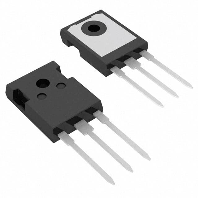
- Package: The IXGH40N60C is typically available in a TO-247 package.
- Essence: It is designed to efficiently handle high power levels while maintaining reliability and performance.
- Packaging/Quantity: The product is usually sold individually or in reels of multiple units.
Specifications
- Voltage Rating (VCES): 600V
- Current Rating (IC): 40A
- Switching Frequency: Up to 20 kHz
- Operating Temperature Range: -55°C to 150°C
- Gate-Emitter Voltage (VGE): ±20V
Detailed Pin Configuration
The IXGH40N60C typically has three pins: 1. Collector (C): Connects to the load or power supply. 2. Emitter (E): Connected to the ground or return path. 3. Gate (G): Controls the switching of the IGBT.
Functional Features
- High Current and Voltage Ratings: Capable of handling high power levels.
- Low Conduction and Switching Losses: Ensures high efficiency in power conversion applications.
- Ruggedness: Withstands harsh operating conditions and transient overloads.
Advantages and Disadvantages
Advantages
- High power handling capability
- Low power losses
- Suitable for high-frequency switching applications
Disadvantages
- Higher cost compared to standard power transistors
- Requires careful consideration of drive circuitry due to high input capacitance
Working Principles
The IXGH40N60C operates based on the principles of controlling the flow of current between the collector and emitter terminals using the gate signal. By modulating the gate voltage, the IGBT can be switched on and off, allowing precise control of power flow in the circuit.
Detailed Application Field Plans
The IXGH40N60C finds extensive use in the following applications: - Motor Drives: Controlling the speed and direction of electric motors. - Inverters: Converting DC power to AC for various industrial and consumer applications. - Power Supplies: Regulating and converting electrical power for different devices and systems.
Detailed and Complete Alternative Models
- IXGH40N60B: A lower-rated version of the same IGBT suitable for applications requiring lower power handling.
- IXGH30N60A: Offers similar performance with slightly lower current and voltage ratings.
In conclusion, the IXGH40N60C is a versatile high-power IGBT that offers efficient power handling and control capabilities, making it suitable for a wide range of power electronic applications.
(Word count: 443)
10 domande e risposte comuni relative all'applicazione di IXGH40N60C nelle soluzioni tecniche
What is the maximum voltage rating of IXGH40N60C?
- The maximum voltage rating of IXGH40N60C is 600V.
What is the maximum continuous collector current of IXGH40N60C?
- The maximum continuous collector current of IXGH40N60C is 40A.
What type of package does IXGH40N60C come in?
- IXGH40N60C comes in a TO-247 package.
What are the typical applications of IXGH40N60C?
- IXGH40N60C is commonly used in applications such as motor drives, inverters, and power supplies.
What is the on-state voltage drop of IXGH40N60C at its rated current?
- The on-state voltage drop of IXGH40N60C at its rated current is typically around 1.8V.
Does IXGH40N60C have built-in protection features?
- No, IXGH40N60C does not have built-in protection features and may require external circuitry for protection.
What is the maximum junction temperature of IXGH40N60C?
- The maximum junction temperature of IXGH40N60C is 150°C.
Can IXGH40N60C be used in parallel to increase current handling capability?
- Yes, IXGH40N60C can be used in parallel to increase current handling capability in high-power applications.
What are the recommended gate drive requirements for IXGH40N60C?
- The recommended gate drive requirements for IXGH40N60C include a gate-to-emitter voltage of 15V and a gate charge of 100nC.
Is IXGH40N60C suitable for high-frequency switching applications?
- Yes, IXGH40N60C is suitable for high-frequency switching applications due to its fast switching characteristics.